 |

|
| Presentation: USC August 2004 | |
| Presentation: May 2004 CLEO Conference | |
 |
Millimeter-wave microphotonic receiver
¯ Small size, small weight, low power consumption.
¯ Optical isolation
¯ No high-speed electronics
The microphotonic RF receiver concept
The microphotonic RF receiver is a novel approach to RF receiver design based on photonic RF signal processing. In our design we combine the idea of direct-conversion (or homodyne as opposed to heterodyne), self-mixing technique and microdisk modulator technology, to directly extract baseband information from the received signal by self-mixing of the transmitted carrier and the sidebands in the optical domain.
The key innovation in the photonic RF-receiver is replacing the function of a single-ended diode or FET mixer in a transmitted carrier wireless link with a sensitive resonant optical modulator that performs down-conversion in the optical domain. In this approach the nonlinear dependence of the modulator’s transmitted optical power (Pot) on applied RF voltage (VRF) is the source of nonlinearity in the system. Fig.1 shows how tuning the laser wavelength to a transmitted resonant dip of the microdisk optical modulator results in square-law operation where Potµ VRF2. The constant of proportionality is determined by the sensitivity of the microdisk modulator and the amount of coupled optical power.

The receiver is designed for a transmitted carrier wireless link where the down-conversion occurs by mixing carrier and sidebands in the optical domain, eliminating the need for an RF local oscillator. So the transmitted carrier power is used for down-conversion (self-mixing) and the baseband is directly extracted without using the intermediate frequency conversion (homodyne reception).
Fig. 2 illustrates the photonic self-homodyne RF receiver architecture. The received RF signal contains both sidebands and the center frequency (transmitted-carrier double-sideband modulation format) and is fed to an optical modulator biased at its nonlinear operating point.

Fig. 2 Schematic diagram of the photonic self-homodyne RF receiver. The transmitted carrier RF signal is received by the antenna and is directly fed to a square-law optical intensity modulator. Through nonlinear optical modulation the optical output intensity spectrum contains the baseband and high frequency components that are filtered out by the response of the low-speed photodetector.
The carrier and sidebands are mixed through the second-order nonlinearity (Po µ VRF2), hence the optical output intensity spectrum contains the baseband and high-frequency products around the second-harmonic of the carrier frequency. A photoreceiver with a bandwidth matched to the baseband signal generates the baseband photocurrent (ip) and automatically filters out the high-frequency components.
Using a sensitive microdisk modulator as a mixer and eliminating the LO reduces the size and power consumption compared to a conventional RF receiver. Since the RF down-conversion occurs in the optical domain there is no need for high-speed photodetector and electronic components. The absence of high-speed electronics in this design facilitates extension of the carrier frequency to mm-wave frequencies.
The LiNbO3 microdisk modulator
Microdisk optical modulator uses high-Q RF and microphotonic electro-optic resonators that are operated in simultaneous resonance. Fig. 3 shows the cross section of a typical LiNbO3 microdisk modulator. The optical resonator is a z-cut LiNbO3 microdisk with optically–polished curved side-walls. Standard evanescent prism-coupling is used to couple laser light into and out of a TE-polarized high-Q optical whispering-gallery (WG) resonance, which exists at the periphery of the disk. We use diamond microprisms for evanescent coupling element. The resonator’s high optical-Q is used to increase the effective interaction length of photons with an applied RF electric-field. . An RF ring resonator fed by a microstripline is designed to overlap and be in simultaneous resonance with the optical field. When combined with a simultaneously resonant RF structure designed to provide voltage gain between the electrodes, a highly sensitive modulator at microwave frequencies is, in principle, achievable. The free spectral range (FSR) of the optical resonator is the center modulation frequency of the optical carrier. The frequency of the RF carrier fRF should be an integral multiple m of the optical FSR such that f0 = 1 / tdisk = nopt2pR / c where tdisk is the optical round-trip time of the disk and R is the disk radius.

Fig. 3 Cross section of a typical LiNbO3 microdisk modulator. High-Q WG optical resonances are excited in the LiNbO3 microdisk modulator. The RF ring resonator, that is side coupled to the microstripline, generates a strong electric field across the traveling wave optical mode. The effective refractive index of the high-Q TE mode is coupled to the RF E-field through the large electro-optic coefficient of LiNbO3 along c-axis. So simultaneous RF-photonic resonance results in very efficient modulation at fRF = FSR.
Fig. 4 shows two different optical coupling schemes, single and double prism coupling. In single prism coupling method, one prism is used to couple light into and out of the microdisk so transmission dips at resonant wavelengths of the resonator are generated as a result of interference between the WG modes and the throughput. In double prism coupling method dips are replaced by peaks since the throughput doesn’t interfere with the modes. For photonics mixing applications the single prism coupling is preferred because at resonance the transmitted optical power is relatively small so during modulation the noise generated by DC optical power is minimized.

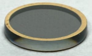
Fig.5 is the photograph of a 5.13 mm diameter and 0.4 mm thick LiNbO3 microdisk modulator with double prism coupling scheme. This modulator has an FSR of 8.7 GHz. The microdisk is mounted on the same substrate as the microstripline therefore the distance between the ring resonator and the microstripline is fixed.
 |
 |
Fig.6 is the photograph of a 3 mm diameter and 0.4 mm thick LiNbO3 microdisk modulator with single prism coupling scheme. This modulator has an FSR of 14.6 GHz. The microdisk is mounted on a separate brass cylinder so the distance between the ring resonator and the microstripline and therefore the RF coupling coefficient is tunable. By optimizing the RF coupling coefficient in this configuration we can optimize the modulator sensitivity. Fig. 7 shows the results of sensitivity measurement for the 14.6 GHz microdisk modulator (Fig. 6). As may be seen in Fig. 7(a) the modulation reaches to the saturation point at 0 dBm RF input power. This shows a 10 dB improvement compared to the best reported result for a 0.15 mm thick microdisk modulator with an FSR of 9 GHz. Fig. 7(b) shows the spectrum of the detected power at –70 dBm (100 pW) RF input power with a signal-to-noise ratio of better than 11dB is measured. The modulation bandwidth is about 80 MHz

Electro-optic microdisk self-homodyne RF receiver
In our first experimental demonstration of photonic self-homodyne data down-conversion we use the 14.6 GHz microdisk modulator in the arrangement shown in Fig. 8. The laser source is a tunable single mode laser with 0.05 pm wavelength resolution and a linewidth of less than 0.5 MHz. The laser wavelength is always tuned to the minimum of the chosen transmission dip to maximize the second-order nonlinear modulation strength. The baseband signal is a 10 Mb/s 27-1 PRBS NRZ data stream mixed with a 14.62 GHz RF-carrier in a double-balanced RF-mixer. By DC-biasing the IF port of the mixer we can control the RF modulation index and magnitude of the transmitted power at carrier frequency. The RF signal is fed to the microdisk modulator through a bandpass RF filter with 1 GHz bandwidth around 14.5 GHz, to make sure that all of the nonlinear products generated in RF components are filtered out. The optical output is detected in a photoreceiver that has a bandwidth of 120 MHz and a sensitivity of –34.5 dBm. Fig. 9 shows the measured BER against the total RF input power. The left inset shows the optical spectrum of the chosen mode that has a Q of 2´106. The right inset shows the input and down-converted data in time domain.

Fig. 8 Schematic diagram of the experimental arrangement used for photonic RF down-conversion measurements. baseband signal is mixed with the 14.6 GHz local oscillator in an RF mixer. The RF filter eliminates any low frequency component generated due to nonlinearities in RF devices. The laser is a tunable single mode laser with a resolution of 0.1 pm and linewidth of less than 0.5 MHz. The baseband modulated optical output is detected by a digital photoreceiver with 120 MHz bandwidth and –34.5 dBm sensitivity.
In Fig. 10 the measured eye diagrams at 10, 50 and 100 Mb/s are shown. The maximum data rate is limited by the optical Q of the chosen mode (»2-3´106) and is typically around 100 Mb/s.


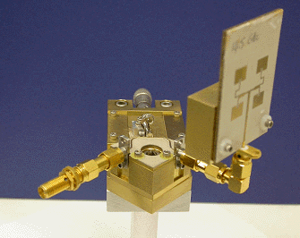
To demonstrate the performance of the photonic self-homodyne in an actual wireless link we have designed a narrowband four-patch antenna array that can be easily attached to the microdisk receiver. Fig. 11 shows a photograph of the antenna coupled microdisk receiver. We used a similar antenna patch array as the transmitting antenna to demonstrate a 10 Mb/s wireless link.

More Information:
You can read more on microphotonic RF receivers in the following papers: